Operation
Induction Furnace Lining: Installation, Sintering and Life
Lining life varies enormously between foundries running identical furnaces. Almost all of the difference is installation practice and the sintering curve.
ForgeLink Engineering Team10 min read
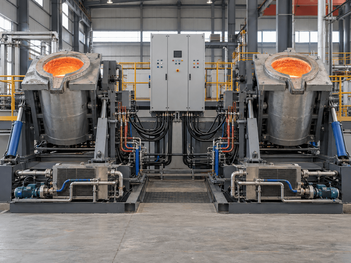
Two foundries can buy the same furnace, the same refractory and the same former, and one will get several times the campaigns out of a lining that the other does. The furnace is not the variable. Ramming density, moisture control and the sintering curve are.
This is the procedure our commissioning engineers teach on site. It is written down here because the single document most often missing from a locally-purchased refractory delivery is the sintering curve for that mix in that furnace size.
Choose the chemistry for your alloy, not for the price
Silica mixes are cheap, expand predictably and work well for grey iron and carbon steel. They lose the argument at high tapping temperatures and against basic slags. Alumina holds up at higher temperature and suits alloy and stainless steels. Magnesia and spinel are for manganese steel and high-slag duties where silica would be attacked chemically.
Buying silica because it is cheapest and then melting high-manganese steel in it is the most common lining failure we are called about. The refractory is not defective; it is the wrong chemistry, chemically attacked exactly as it should be.
Ramming density is the whole job
Refractory is added in layers of 50–80 mm and vibrated until the surface stops moving and takes on a slight sheen. Too little compaction leaves porosity that slag penetrates; too much on a silica mix crushes the grain distribution and destroys the expansion behaviour the lining depends on.
The most common error is going too fast — pouring in 200 mm of dry mix and vibrating the top. The lower part never densifies, and the lining fails from the inside in the first few campaigns. There is no way to inspect for it afterwards, which is why we install the first lining ourselves and supervise your team on the second.
- Layers of 50–80 mm, never more
- Vibrate each layer until the surface stops moving
- Keep the former centred and check it after every two or three layers
- Keep the mix dry — a damp bag is a scrapped lining
The sintering curve is not optional
Sintering forms the three zones a working lining needs: a fully sintered face against the metal, a transition zone, and a loose backing layer against the coil that lets the lining move without cracking. Rush the curve and you get either a lining that never sinters properly, or one sintered right through to the coil that cracks on the first thermal cycle.
The curve is specific to the mix and the furnace size, so a generic one is worse than none. It typically involves a slow initial ramp to drive off moisture, a hold at an intermediate temperature, then a controlled rise to the sintering temperature with a defined dwell before the first working heat.
Monitoring life and knowing when to change
Track two things: heats since installation, and the metal volume at a known tap temperature. As the lining wears, the furnace holds more metal — a measurable, objective signal that beats visual inspection. A thickness gauge or a lining-monitoring system gives you the same information more directly.
Set a change-out point and hold to it. The cost of a planned lining change is a scheduled shift. The cost of a run-through is the coil, the surrounding equipment, and potentially someone's safety. That trade is never worth taking, and it is why the dual-track configuration pays for itself in foundries that would otherwise be tempted to push a lining one campaign too far.
Common causes of short lining life
When a customer reports lining life well below expectation, it is almost always one of these five, in this order of frequency.
- Under-rammed lower layers from adding refractory too fast
- Sintering curve shortened to get back into production
- Wrong chemistry for the alloy or the slag practice
- Excessive tapping temperature, often to compensate for a slow pouring line
- Long holding periods at temperature between pours